Description
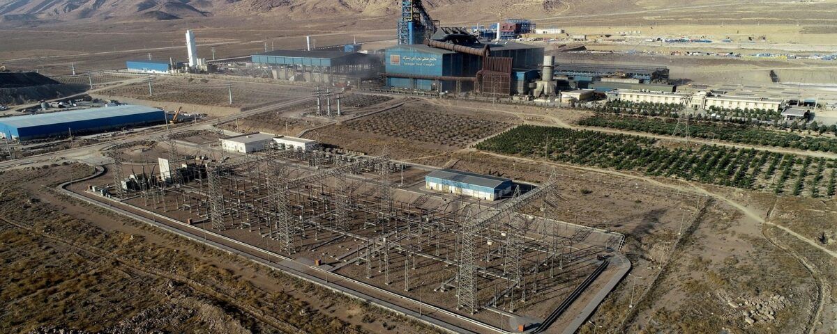
Zob Ahan Pasargad Industrial Company (private joint stock) belonging to the private sector with the aim of creating a complete steelmaking. complex from the stage of receiving iron ore from the mine to the production of all kinds of alloy steels in accordance with international standards. in Shiraz, on the south side of Maharlo lake (Shiraz-Jahrom road) It has been built on a land of three million square meters.
From the beginning, the design of this factory has been such that only iron ore is received from the country’s mines and all subsequent stages include: iron ore crushing and concentration. Converting production concentrate into pellets, converting pellets into sponge iron. and converting a part of sponge iron into molten steel and converting raw steel into various types of alloy steels through secondary metallurgy using a crucible furnace (LF) and a vacuum degassing unit (VD) or a carbon unit Vacuum extraction (VOD) takes place.
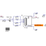
1. Thermal Decomposition of C1 to C5 in Iron Melting Furnace
Long furnace is a vertical furnace. which is used in metal smelting factories to extract metal, especially iron, from ore. The blast furnace is considered as the most original method of separation from iron ore. Along with iron ore, coke and agglomerate, it is poured into the blast furnace. In a solid fuel blast furnace, usually coke burns with air blowing and melts the minerals.
Modern furnaces are very efficient. and one of the reasons for this is the use of a recovery system to use the heat of the gases coming out of the blast furnace, increasing the air pressure,. and injecting coke powder. Another reason is the increase in the amount of oxygen entering the furnace.
These factors have increased the production of iron, the amount of exothermic gases and the volume of coke used in the furnace. The largest iron blast furnace system in the world is located in South Korea, which has a volume of 6,000 cubic meters. This furnace can produce about 5650,000 tons of iron per year.
2. Explanatory Plan and Estimate of Implementation Costs of LPG Fuel Replacement Unit
Liquefied gas or LPG refers to two hydrocarbon gases, butane and propane, or their combination, which are kept in a liquid state. Usually, small amounts of compounds such as propylene and butylene are also present in liquid gas. LPG is mostly used for heating applications and as fuel for vehicles. It is also used in the manufacture of sprinklers and as a cooling gas in refrigerators and freezers. In oil and gas refineries, LPG is a byproduct of natural gas and crude oil refining.
The calorific value of liquid gas is 46.1 MJ/kg, which is higher than gasoline and fuel oil. And it produces higher energy in the same weight, but its calorific value is lower in the same volume because it is a gas. and less dense. Each liter of liquid gas weighs 500 to 580 grams and each liter of gasoline weighs 710 to 770 grams.
This gas turns into a liquid at a temperature of 21 degrees Celsius under a maximum pressure of 8 kg/cm2. And at the time of production, it lacks color, smell, and even taste, and for greater safety, sulfur-containing compounds called mercaptan (which includes ethyl mercaptan and methyl mercaptan) are added to it.
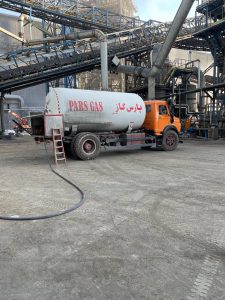
For industrial purposes, LPG is used in larger tanks that are installed in the industrial production site. These tanks are filled by liquefied gas transporters directly from the refinery or liquefied gas distribution companies.
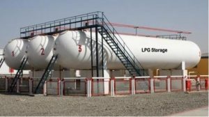
The figure below shows the LPG fuel tank supplied by Petroparsian Abraj.

Price and Access for Pasargad Iron Melting Complex
CNG gas is usually cheaper than LPG. But it should be noted that the energy content of LPG is actually more than twice that of CNG. So in general and without taking into account possible government subsidies. Apply to some fuels in some countries. LPG is more economical to use than CNG.
Also, LPG is stored in liquid form in special cylinders. And its retail sale is easier and generally more accessible for the factory and the purpose of implementing this project. While CNG is provided to the supply centers in several stages through the pipeline system from the wells through the valves of the refineries.
Therefore, the availability of LPG in retail form is easier. On the other hand, in order to use injected carbon in the furnace of iron pellets, the goal is to inject LPG into the furnace, which contains much more carbon than city gas.
3. Simulating The Process of Reforming and Production of Synthesis Gas in Order to Inject Into Pellets
The reforming reaction is completed by injecting air into the secondary reformer, and at the same time, the nitrogen required for the ammonia reaction enters the process cycle through air. Carbon monoxide along with the process gas is converted into CO2 in the next steps and the resulting mixture is directed to the CO2 absorption section for purification. CO2 gas is a by-product of ammonia production units, which after separation, is sent as feed to urea units.
Reforming Reactions
In this alternative plan, instead of using large LPG tanks, it is necessary to design a new reforming unit. which provides the carbon monoxide required for the process for the pellets. The technical knowledge of this new process is at the disposal of Petroparsian Abaraj Company. And regarding the required studies, the details of this process will be presented in full in future reports.
The main feed of this new process is natural gas along with carbon dioxide gas. the product of which produces a large amount of carbon monoxide. The output ratio of hydrogen to carbon monoxide is 0.98 to 1. In order to supply the required carbon dioxide, the BDCL process or the chemical combustion cycle can be used. The figure below shows the BDCL process.
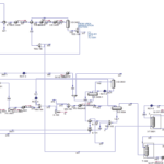
4. Investigation Report on Non-Extraction of Pentane From City Gas
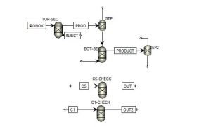
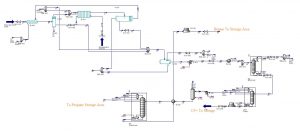
The simulation of this unit has also been done in Aspen Hysys software. In this unit, C1, C2 is separated from the gaseous composition C1, C2, C3, C4, C5 in the first tower. And it is sent to the tanks of 9300 units, which is Kangan natural gas. Next, in the second distillation tower, C5, which is a heavier compound, is separated. And then C3 and C4 are sent to the propane and butane tanks in a completely concentrated form with high grade.
According to the report provided from industrial data and detailed simulations with the help of powerful software, it is clearly clear. that the possibility of extracting gases heavier than methane from city gas was not possible either economically or practically. The amount of separation of propane gas from city gas is 3.5 mole percent per unit of input flow rate of city gas in the most possible case.
To reach the goal of our process which is about 4000 normal cubic meters per hour. (on average) in practical mode, city gas flow rate of 114,000 normal cubic meters per hour (2800% more) of city gas should be used so that the output of propane reaches the same minimum required amount. With fingertip calculations on these numbers without the need to calculate the price, it is clear that this project cannot be implemented with Municipal gas feed.
Of course, if the above problem is solved, separation processes with a very high recovery rate are needed to reach the ideal goal of this project. Because of this, operational conditions have become very difficult, as a result of which the cost of distillation towers has increased drastically and the cost of initial investment has also increased drastically.
5. Evaluation of The Design Costs of The Entire LPG Supply Unit
Each industrial unit must first have a detailed design on it. And certainly there is no industrial unit in the whole world that starts working without initial design and preparation of basic industrial plans and documents. It should be noted that in this project, the design cost estimate is provided. The first step is the implementation of this project in Pasargad iron melting industrial complex.
The detailed design steps are presented in a table in the order of the work and the design process. This table, which we will discuss in more detail below, has detailed and considered steps for the implementation of this project.
Now, it should be noted that in all the steps mentioned in the table, there may be a need for corrections to be made by the technical staff of engineers of the Iron melting Complex. In fact, the general purpose of the complete design is:
Preliminary design of the process and review of operating conditions
Plot design and placement method
Accurate simulation and obtaining the process data sheet
Preparation of industrial plans and important documents such as: PFD, PID,….
The detailed design of the equipment in the final operational conditions is registered
Information of all industrial equipment or in other words Equipment data sheet
3D design and material purchase list (MTO)
Getting the output of isometric maps to implement piping accurately with the least possible error.
Output of executive maps
Examining the strengths and weaknesses of the design
Checking the safety points of the entire process with HSE specialists and HAZOP review
Full monitoring of the project implementation and elimination of other possible risks during implementation
6. General Proposals for The Injection Fuel Replacement Unit to Supply The Carbon Source Required for Sponge Iron
The First Plan: Liquefied Gas (LPG)
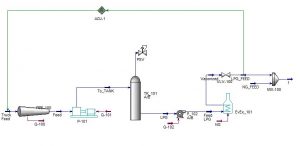
Design of the process has been done according to the request and preliminary. approval of the engineers of the technical office and control room of the iron melting plant of the reclamation unit. Place considered for the design of the factory is an area of about 65 x 65 square meters in the vicinity of the reforming unit of the factory. In this process, first tanker unloading station will be placed by a P_101 pump.
In this process, first the tanker unloading station will be placed by a P_101 pump. Then the desired fluid is sent to multiple parallel tanks (2 or 4 horizontal tanks) TK_101, TK_102, TK_103, TK_104 and stored. Then, each tank is sent to the main parallel pump P_102 A/B with the help of branching in the condition of being in the main delivery line of the pipes.
After an EVEX_101 vaporizer, it instantly turns the incoming liquid into gas. And with the help of a K_101 compressor, the pressure has increased a little. And then by passing through the control valve, the desired flow rate and pressure is reached and it is injected into the furnace.
Process Diagram
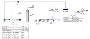
The simplified process Diagram of the above process is shown in the figure below. It should be noted that this was for preliminary study. And after doing the simulation in the next chapters, he completed this process accurately and with a complete report. And by recording the correctness of the action, the process is finalized and sent to the explanatory plan department as an implementation. To make economic calculations to calculate the estimated price of implementing this system.
The Main Components of The Alternative Fuel Station
Unloading and loading
Primary pump to send to storage tanks
Secondary pump station to send LPG to vaporizer
LPG vaporizer
Compressor
Pressure reduction
Combination of butane and propane gas with methane (mixer) for injection into the main reactor
Safety and fire fighting
Instrumentation and signals sent to the control room
Electricity for all stations
1. Schematic of The Process

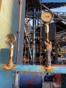
2. Temperature and Pressure Gauge
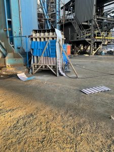
3. Evaporator
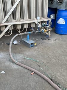
4. Temperature and Pressure Gauge Before The Evaporator
The Second Plan: Replacing The Secondary Reforming Unit in Order to Provide CO (New Design of The DPIZER Unit)
In this alternative plan, instead of using large LPG tanks, it is necessary to design a new reforming unit. which provides the carbon monoxide required for the process for the pellets. Technical knowledge of this new process is at the disposal of Petroparsian Abaraj Company, and details of this process will be presented in full in future reports regarding the required studies.
The main feed of this new process is natural gas along with carbon dioxide gas, the product of which produces a large amount of carbon monoxide. The output ratio of hydrogen to carbon monoxide is 0.98 to 1. In order to supply the required carbon dioxide, the BDCL process or the chemical combustion cycle can be used.
The Third Plan: Diesel Injection Instead of LPG
Another proposed process to supply the required carbon source is to inject diesel instead of LPG gas. GasOil is one of the relatively heavy products of crude oil and is obtained after kerosene in the distillation tower.
Diesel is one of the fractions that are produced both in the atmospheric distillation tower and the vacuum distillation tower. Also, many refinery units, such as cracking, hydrocracking and coking units, produce diesel in addition to gasoline by changing the structure of heavy oil cuts.
Diesel is a colorless liquid, and in order to recognize it and distinguish it from other liquids and products, its color is changed. And they turn brownish in color. Diesel is a mixture of different hydrocarbons that have between 14 and 20 (even up to 25) carbon atoms in their molecular structure.
The most important application of diesel is as a fuel for diesel engines, heating facilities and fuel for some factories. The compression ratio of diesel engines is much higher than gasoline engines. Therefore, more power can be obtained from a diesel engine and these engines are used for heavy vehicles.
Due to the confidentiality of this project, it is not possible to provide input information and output results.
